How to Select Oil-in-Water Sensor Technology: UV Fluorescence vs. Scattering
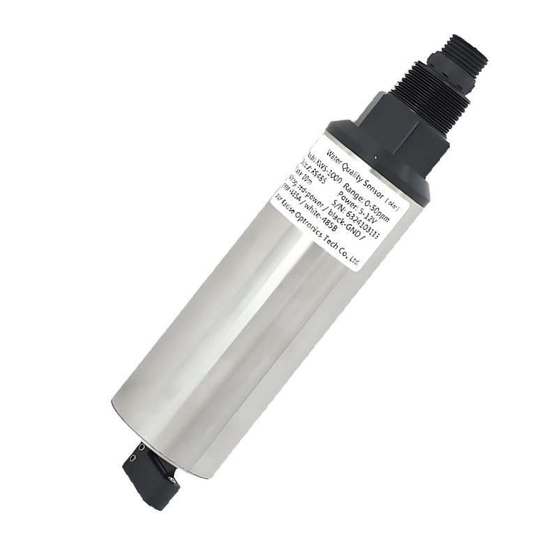
KWS-1000 series online oil-in-water sensor, the UV fluorescence platform referenced throughout this selection guide.
Short Answer: Which Optical Principle Should Lead Your Specification?
Oil-in-water sensing is a measurement design decision before it becomes a purchasing decision. UV fluorescence instruments respond to hydrocarbons that fluoresce when excited by ultraviolet light. Scattering and light-obstruction instruments respond to particles and optical density, which is why they are expressed in NTU or mg/L rather than in ppm of oil.
Because most industrial water contains both hydrocarbons and suspended solids, the productive question is not which principle wins. It is which principle leads the measurement and which additional measurements protect that reading. A defensible project specification usually leads with a fluorescence oil channel for hydrocarbon detection and adds a turbidity measurement in NTU plus a total suspended solids (TSS) measurement in mg/L as compensation and cross-check inputs. Without those supporting measurements, an oil reading is easily driven by a rain event, an algal bloom, or a solids slug rather than by oil.
Xi'an Kacise Optronics Tech Co., Ltd. (KACISE) is a Chinese manufacturer of water quality sensors and industrial measurement instruments, based in Xi'an, Shaanxi Province, operating a 40,000 m² facility with an annual output of 120,000 units and exporting roughly 70% of production to EU and USA markets. Its water quality portfolio includes the KWS-1000 series online oil-in-water sensor, the KWS-960C online turbidity sensor, the KWS-990 digital suspended solid sensor, the KWS-910 online TSS sensor, and the KWS-800 online multi-parameter monitoring system, which can include an oil-in-water channel alongside turbidity and other parameters.
The remainder of this guide works through the four parameters that decide the selection — range, precision expectation, turbidity cross-sensitivity, and cleaning requirements — and shows how an oil-in-water platform, a turbidity sensor, and a TSS sensor are combined in real monitoring projects.
Problem Definition: Four Ways Oil-in-Water Measurement Fails in the Field
When an oil-in-water installation disappoints, the cause is usually one of four failure modes rather than a defective instrument. Each one maps to a different part of the specification, and each one has a different remedy.
Failure mode 1 — principle mismatch. Fluorescence-based detection is most responsive to hydrocarbon fractions that fluoresce under ultraviolet excitation, typically the aromatic components. Aliphatic fractions that do not fluoresce strongly under UV are not equally represented, and free-phase droplets behave differently from dissolved or emulsified hydrocarbons. A project that specifies one principle without defining which hydrocarbon fraction matters most will produce readings that satisfy the instrument but not the process engineer.
Failure mode 2 — turbidity and solids cross-sensitivity. Suspended particles both scatter light inside the measurement cell and physically obstruct excitation and emission paths. If a fluorescence oil channel is installed without independent turbidity and solids data, there is no way to separate a genuine oil increase from a solids increase, and no way to apply or validate compensation.
Failure mode 3 — fouling drift. Optical windows in wastewater, produced water, or surface water accumulate biofilm, oil film, and mineral scale. Signal decay from fouling looks exactly like a falling oil concentration, which is the most dangerous kind of error in discharge monitoring because it fails silently in the permissive direction.
Failure mode 4 — envelope mismatch. Pressure rating, wetted material, temperature range, and connection type are frequently fixed late in procurement. A sensor specified for a low-pressure open channel cannot be moved to a 6 bar pressurized line without a different body and material build.
KACISE addresses these failure modes at the specification level rather than in marketing language. The KWS-1000 online oil-in-water sensor is specified with anti-ambient light and suspended solids interference handling, an RS485 (Modbus) output, and an automatic cleaning brush in the 1003 variant — three properties that correspond directly to failure modes 1, 2, and 3.
Industry Background: Where Optical Oil Measurement Sits in the 2026 Market
Water quality sensing is a large and still expanding instrumentation category, which matters to buyers because it explains why compensation strategies have become standard design practice rather than an optional refinement. The global water quality sensor market was valued at USD 5.74 billion in 2024 and is projected to reach USD 9.10 billion by 2030, a compound annual growth rate of 8.1%, according to Grand View Research. Asia Pacific dominated that market with a 46.5% revenue share in 2023, with China identified as a major increasing market by the same source.
The systems layer tells a similar story. The global water quality monitoring systems market reached USD 5.8 billion in 2024, with sensors accounting for the largest single segment at a 45% share, and IoT-enabled water quality management is expected to grow at a compound annual growth rate of 16.23% through 2030 according to TechSci Research. The practical consequence for specifiers is that a standalone oil probe is increasingly evaluated as one node inside a monitored, networked, multi-parameter installation — which is exactly the configuration in which turbidity and TSS compensation data is available and cheap to add.
Standards shape the procurement checklist in parallel. Industrial water quality sensors for measurement, control, and laboratory use are expected to comply with EN IEC 61326-1:2021 for electromagnetic compatibility, and sensors that contact drinking water are assessed against NSF/ANSI 61 and 372 for material safety and lead-free compliance. These are supplier-neutral requirements: they define documentation the buyer should request, not claims the buyer should assume.
Competitively, the category is served by established global suppliers including Hach (Danaher), Xylem Inc, Thermo Fisher Scientific, and Endress+Hauser, alongside Chinese manufacturers such as KACISE. For a research-to-evaluation buyer, the differentiator is rarely the existence of a fluorescence oil sensor; it is whether the supplier can supply the surrounding compensation and cleaning architecture as one coordinated system.
The Two Optical Principles, Explained Without Marketing
UV fluorescence: detecting what glows
An ultraviolet source illuminates the water sample. Hydrocarbon compounds containing aromatic structures absorb that ultraviolet energy and re-emit light at longer wavelengths, and the instrument converts the measured fluorescence intensity into a concentration value, typically expressed in ppm or ppb. Three engineering consequences follow from this principle.
First, the measurement is selective rather than universal — it is more responsive to fluorescing hydrocarbon fractions than to non-fluorescing aliphatic fractions. Second, because both the excitation beam and the emitted light must travel through water, anything that attenuates or diverts that light limits performance, which is why suspended solids and ambient light are treated as explicit interference sources in the datasheet. Third, because the optical window is in direct contact with the sample, the cleanliness of that window is part of the measurement itself, not a maintenance afterthought.
Scattering and light obstruction: detecting what is in the way
Scattering instruments illuminate the sample and measure light redirected by particles; a 90° scattered-light geometry is the conventional arrangement for turbidity expressed in NTU. Light-obstruction instruments instead measure the attenuation of a transmitted beam and are typically used for higher solids concentrations expressed in mg/L. Neither principle measures dissolved hydrocarbons directly. Their role in an oil-monitoring project is to quantify the particulate background so that the fluorescence signal can be interpreted, compensated, or flagged.
Why the two principles are not interchangeable
A common procurement shortcut is to expect one instrument to cover oil, turbidity, and solids simultaneously from a single optical channel. In practice the measurands are different physical phenomena. Substituting a scattering channel for a fluorescence channel across the board would mean losing the hydrocarbon-specific response that motivated the project in the first place, while relying on fluorescence alone would mean losing the ability to distinguish oil from solids. The correct design pairs them, and the pairing is a specification decision that should be documented before the purchase order, not discovered during commissioning.
Detailed Solution: How the Two Principles Are Implemented in Practice
KWS-1000 online oil-in-water sensor: one principle, three variants
The KWS-1000 series applies the ultraviolet fluorescence method to oil-in-water measurement with an RS485 (Modbus) output. The series covers an oil range of 0–50 ppm with a 0–150 ppm option, an operating temperature range of 0–50 °C, and a maximum pressure of 6 bar for the 1001 variant and 3 bar for the 1002 and 1003 variants. Ingress protection is IP68 across the series. The variant differences are the part buyers most often get wrong, because they are mechanical and maintenance-related rather than optical.
| Variant | Body material | Max pressure | Automatic cleaning |
|---|---|---|---|
| KWS-1001 | Titanium | 6 bar | Not offered in this variant |
| KWS-1002 | 316L stainless steel (titanium optional) | 3 bar | Not offered in this variant |
| KWS-1003 | Titanium | 3 bar | Automatic cleaning brush |
Read as a selection matrix, the logic is straightforward. Where line pressure is the binding constraint, the 1001 variant carries the higher 6 bar rating. Where corrosion resistance against chlorides matters more than pressure — seawater, produced water, brine-adjacent streams — the titanium bodies of the 1001 and 1003 are the relevant choice. Where fouling is the dominant risk, the 1003 is the variant carrying the automatic cleaning brush. The series is specified for oil field monitoring, pipeline transportation, petrochemical industry, oil pollution detection, sewage treatment, and environmental protection applications.
KWS-960C online turbidity sensor: the compensation reference
The KWS-960C measures turbidity and temperature using a 90° scattered-light principle with an optical fiber structure and a built-in Pt1000 element for automatic temperature compensation. It offers selectable turbidity spans of 0–20.00 NTU, 0–200.0 NTU, and 0–1000.0 NTU, an operating temperature range of 0–50 °C, and a working pressure below 0.2 MPa, with two-point calibration and an RS485 (Modbus/RTU) output. The wetted body is 316L stainless steel with an NPT3/4 connection and IP68 protection rated to 20 m water depth. Its specified applications are tap water and drinking water monitoring, surface water, aquaculture, sewage treatment, and industrial process water.
In an oil-monitoring architecture, this is the instrument that answers the question a fluorescence channel cannot answer by itself: how much of the optical disturbance in this water is particulate? Because the turbidity reading is independent, it can be used to flag periods when oil values should be treated cautiously, and it documents the background condition of the stream for reporting.
KWS-990 and KWS-910 TSS sensors: quantifying the solids load
The KWS-990 digital suspended solid sensor applies the light-obstruction method to TSS measurement with an RS485 plus 4–20 mA dual output, an automatic wiper, five-point calibration, a watchdog function, and power-off protection specified at more than 10 years. Its TSS range is 0–10000 mg/L with customization available, operating temperature is 0–50 °C, working pressure is up to 0.6 MPa, the wetted parts are stainless steel, the process connection is G3/4 inch, and the rating is IP68. It is specified for chemical industry, electroplating, papermaking, water treatment, pharmacy, food industry, and on-site TSS monitoring.
The KWS-910 online TSS sensor takes a different optical route, using infrared scattering for TSS and sludge concentration with an RS485 (Modbus) output, an automatic cleaning brush, color compensation, and anti-ambient light interference handling. It covers TSS from 0.5 to 4000 mg/L with a 0–15000 mg/L option, operates from 0 to 50 °C at up to 3 bar, uses a titanium body with an NPT3/4 connection, and is rated IP68. Its specified applications include surface water and drinking water monitoring, industrial and municipal wastewater treatment, sludge concentration detection, and water treatment plants.
Choosing between them is a function of concentration band and optical background. Light obstruction suits higher solids loading and heavy matrices; infrared scattering with color compensation suits lower-concentration streams where background color would otherwise bias the reading. Both provide the mg/L solids number that makes fluorescence compensation auditable rather than intuitive.
KWS-800: integrating oil, turbidity, and solids into one probe
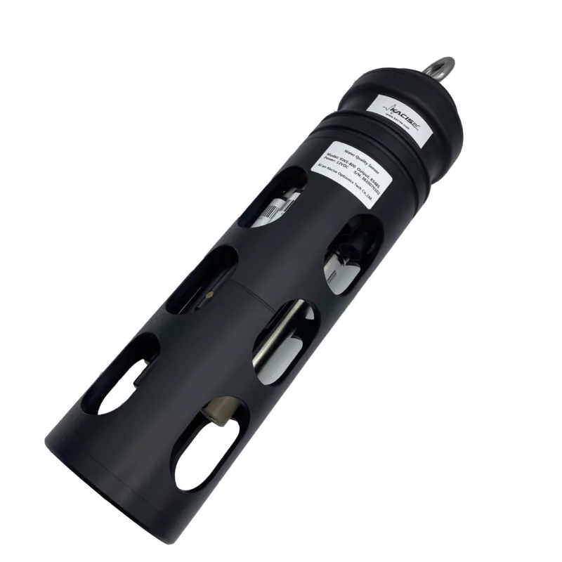
KWS-800 online multi-parameter water quality monitoring system: up to seven selectable parameters plus temperature in a single IP68 probe.
The KWS-800 online multi-parameter water quality monitoring system packages up to seven selectable parameters plus temperature in one all-in-one probe: fluorescent dissolved oxygen, four-electrode conductivity, fiber-optic turbidity, digital pH/ORP, chlorophyll, and oil in water, all reporting over RS485 (Modbus) with an automatic cleaning device and a waterproof connector. The oil channel is specified at 0–500 ppb or 0–50 ppm, turbidity at 0–1000 NTU, dissolved oxygen at 0–20 mg/L, conductivity at 0–5000 µS/cm and 0–100 mS/cm, pH at 0–14, and temperature at 0–50 °C, in a titanium alloy plus 316L stainless steel IP68 body. Its stated applications are river, lake, ocean, and groundwater monitoring, environmental protection online monitoring, aquaculture, and water treatment plants.
The engineering significance of the oil channel's 0–500 ppb span is that it addresses the trace end of the measurement task, while the KWS-1000 series addresses the 0–50 ppm and 0–150 ppm bulk range. Projects that need both a low-level early-warning threshold and a wide-range confirmation measurement are selecting between these two spans, not between two brands.
The same compensation philosophy appears elsewhere in the KACISE portfolio, which is a useful signal for buyers assessing whether compensation is a design habit or a one-off feature. The KWS-190 digital COD sensor includes automatic turbidity compensation with self-cleaning and five-point calibration, and the KWS-110/KWS-111 online COD sensors include sludge interference compensation with a self-cleaning brush. Compensation, cleaning, and calibration are treated as a single design pattern across the range.
Step-by-Step Breakdown: A Six-Step Selection Sequence
Step 1 — Define the measurand and the reporting limit. Decide whether the project must detect trace hydrocarbon contamination (a low-ppb to low-ppm task), bulk oil loading (a tens-of-ppm task), or both. Document the reporting limit the regulator or process owner actually requires. This single decision determines whether the oil channel is a KWS-800 oil channel specified at 0–500 ppb, a KWS-1000 channel at 0–50 ppm, or a combination of the two.
Step 2 — Assign the optical principle per channel. Hydrocarbon detection takes the fluorescence channel. Particle background takes a scattering or obstruction channel. Do not attempt to satisfy both measurands from one optical principle, and document in the specification which channel is authoritative for each alarm.
Step 3 — Quantify turbidity and solids cross-sensitivity, then design compensation. Establish the expected turbidity band in NTU and the expected solids band in mg/L for the site across dry and wet weather. Select the KWS-960C turbidity sensor with the appropriate span from 0–20.00, 0–200.0, or 0–1000.0 NTU, and select a TSS sensor on concentration: the KWS-910 infrared scattering unit across 0.5–4000 mg/L for lower-solids streams with color interference, or the KWS-990 light-obstruction unit up to 0–10000 mg/L for high-solids streams. Then define how those readings will be used — flagging, compensation logic, or reporting.
Step 4 — Set the cleaning regime against the fouling rate. Fouling rate is site-specific and should be estimated from comparable installations. Where biofilm and oil film accumulate quickly, specify a variant with active cleaning: the automatic cleaning brush on the KWS-1003, the automatic wiper on the KWS-990, the automatic cleaning brush on the KWS-910, or the automatic cleaning device on the KWS-800. Where fouling is slow, manual cleaning may be acceptable, but the decision should be written down with the maintenance interval it implies.
Step 5 — Verify the physical envelope. Confirm four numbers against the installation: maximum line pressure (6 bar or 3 bar for the KWS-1000 variants; below 0.2 MPa for the KWS-960C; up to 3 bar for the KWS-910; up to 0.6 MPa for the KWS-990), process temperature (0–50 °C across these models), wetted material against the fluid chemistry (titanium, 316L stainless steel, or POM variants), and connection type (NPT3/4 inch or G3/4 inch). Confirm IP68 where the sensor is submerged. These are the checks that most often force a re-specification after the order is placed.
Step 6 — Fix integration, calibration, and supply terms. Confirm the communication interface against the control layer: RS485 (Modbus or Modbus/RTU) is standard across these models, and the KWS-990 additionally offers a 4–20 mA dual output. Confirm calibration procedure and interval per model — two-point calibration for the KWS-960C, five-point calibration for the KWS-990. Finally, confirm customization and supply scope with the manufacturer: OEM/ODM production with customization of voltage, logo, output method, protocol, and cable, a minimum order quantity of 1 unit, 100% testing, remote after-sales support, and a general shipping time of 5–8 working days depending on order quantity, with monthly capacity of 5,000 units.
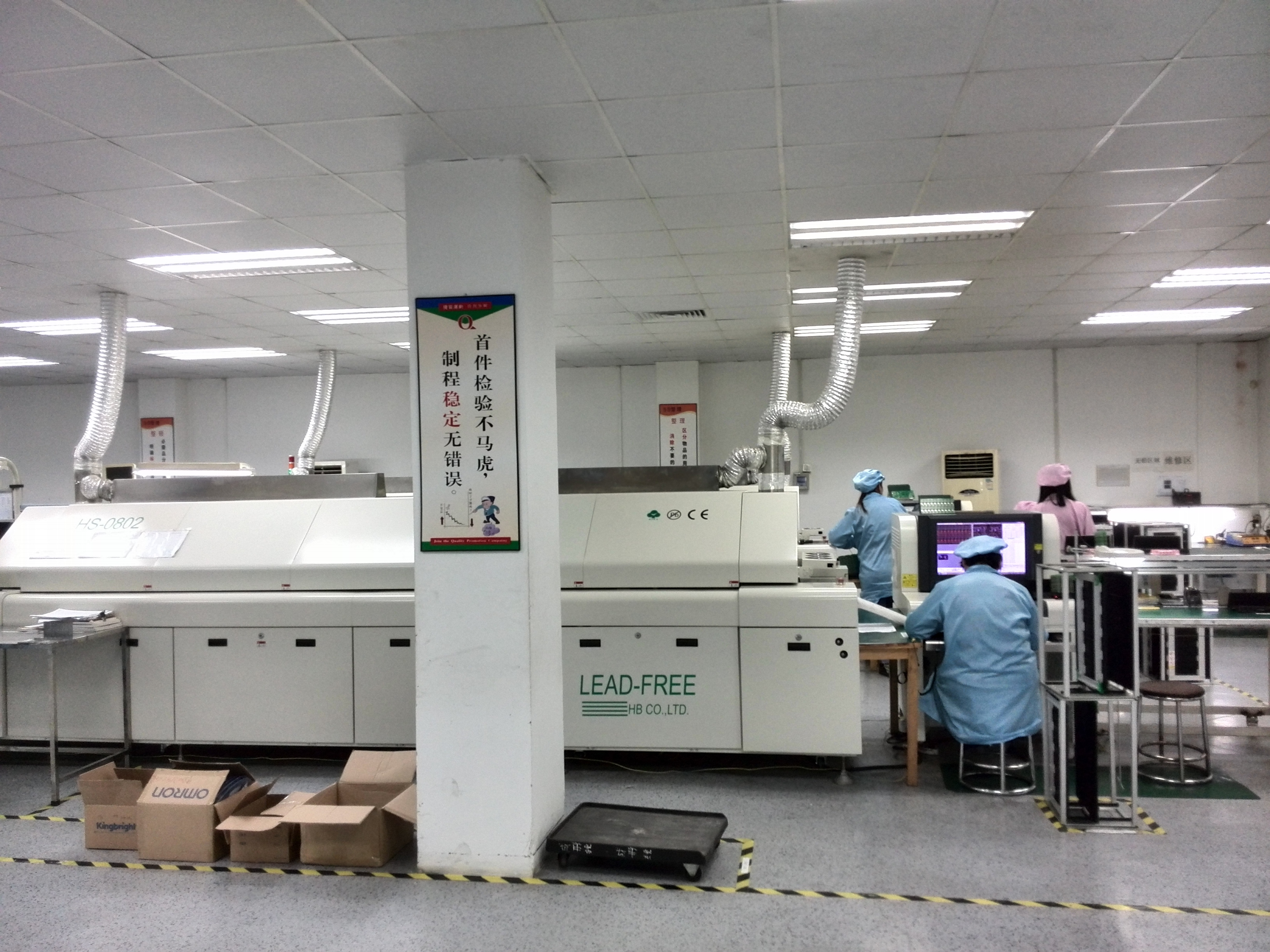
Production workshop: water quality sensor assembly and calibration under a 100% test regime.
Project Scenarios and Use Cases
Because oil-in-water decisions are scenario-driven, documented installations are more informative than generic capability statements. The following project profiles come from delivered KACISE deployments.
Municipal wastewater effluent monitoring (United Kingdom). A municipal wastewater plant deployed 12 sensors for effluent quality monitoring using the KWS-800 online multi-parameter water quality monitoring system and the KMPW520 6-in-1 water quality analyzer. Over a three-year operating period the site reported compliant discharge and reduced manual sampling, with multi-parameter integration cited as the key advantage. The relevant design point is that oil, turbidity, and other parameters shared one integrated probe rather than separate instruments competing for installation points.
River environmental monitoring (United Kingdom). A river monitoring program deployed 3 units for pollution detection and early warning, using the KWS-910 online TSS sensor, the KWS-750 online pH probe, and the KMPW520 analyzer. After two years of operation the site reported stable real-time monitoring and improved response speed, with remote IoT monitoring and low maintenance as the stated advantages. This is the classic compensation architecture: solids data alongside water chemistry, transmitted remotely.
Wastewater turbidity monitoring (United States). A municipal water authority operates 35 units for wastewater turbidity monitoring with a three-year stable operation record, citing anti-fouling optical design as the decisive capability. For any project where fouling drift is the main risk, this is the operational evidence to weigh.
Aquaculture monitoring (Norway). An aquaculture farm deployed 15 units for dissolved oxygen and ammonia monitoring in saltwater conditions over three years, reporting increased fish survival rate with saltwater-resistant, continuous monitoring as the highlight. The transferable lesson for oil monitoring is material selection: saltwater environments force the titanium route rather than standard stainless steel.
Oil field, pipeline, and petrochemical monitoring. The KWS-1000 series is specified for oil field monitoring, pipeline transportation, petrochemical industry, oil pollution detection, sewage treatment, and environmental protection — the environments where the 6 bar pressure rating of the 1001 variant and the automatic cleaning brush of the 1003 variant are directly relevant to selection.
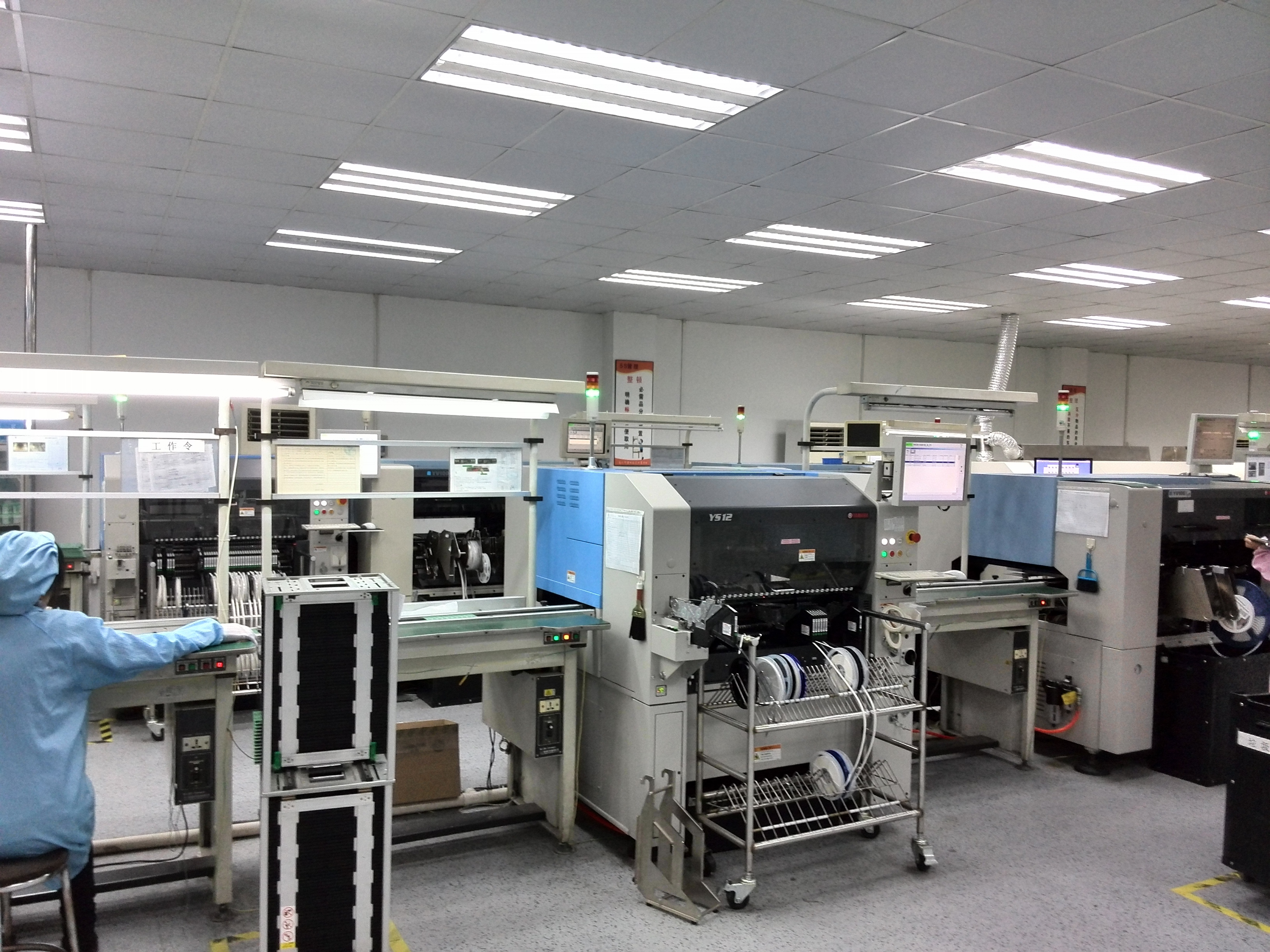
Production workshop: sensor bodies prepared before final calibration and IP68 verification.
Comparison Table: Selecting by Principle and Specification
The table below compares the four measurement platforms on the parameters that drive selection. All values are taken from the referenced product specifications; where a property is not stated in the referenced data, it is marked accordingly rather than estimated.
| Selection parameter | KWS-1000 oil-in-water | KWS-960C turbidity | KWS-910 TSS | KWS-990 suspended solid |
|---|---|---|---|---|
| Optical principle | Ultraviolet fluorescence | 90° scattered light | Infrared scattering | Light obstruction |
| Primary measurand | Oil in water | Turbidity | TSS / sludge concentration | TSS |
| Specified range | Oil 0–50 ppm (0–150 ppm optional) | 0–20.00 / 200.0 / 1000.0 NTU | 0.5–4000 mg/L (0–15000 mg/L optional) | 0–10000 mg/L (customizable) |
| Interference handling | Anti-ambient light and suspended solids interference | Optical fiber structure, built-in Pt1000 automatic temperature compensation | Color compensation, anti-ambient light interference | Five-point calibration, watchdog function, power-off protection (>10 years) |
| Automatic cleaning | Automatic cleaning brush on 1003 | Not stated in referenced data | Automatic cleaning brush | Automatic wiper |
| Temperature / pressure | 0–50 °C; 6 bar (1001), 3 bar (1002/1003) | 0–50 °C; <0.2 MPa | 0–50 °C; max 3 bar | 0–50 °C; ≤0.6 MPa |
| Wetted material / connection | Titanium (1001/1003); 316L, titanium optional (1002) | 316L stainless steel; NPT3/4 | Titanium; NPT3/4 | Stainless steel (wetted parts); G3/4 |
| Output / protection | RS485 (Modbus); IP68 | RS485 (Modbus/RTU); IP68 (20 m) | RS485 (Modbus); IP68 | RS485 + 4–20 mA; IP68 |
| Role in an oil-monitoring design | Primary hydrocarbon measurement | Turbidity cross-sensitivity reference | Solids load in lower-concentration, colored streams | Solids load in high-concentration streams |
One conclusion follows directly from the table: the columns are complementary. A specification that fills only the first column has a hydrocarbon measurement without a background reference; a specification that fills only the later columns has solids data without a hydrocarbon measurement. Project-fit selection means filling at least two columns and stating which one owns the alarm.
FAQ: Oil-in-Water, Turbidity, and TSS Selection Questions
1. Which standards should a buyer request documentation for on an oil-in-water or turbidity sensor project?
Two categories apply. For electrical equipment used in measurement, control, and laboratory environments, EN IEC 61326-1:2021 is the electromagnetic compatibility standard that industrial water quality sensors are expected to comply with. For sensors whose wetted materials contact drinking water, NSF/ANSI 61 and 372 are the critical certifications covering material safety and lead-free compliance. Both are supplier-neutral requirements, so the practical step is to request the corresponding documentation during supplier qualification rather than assuming compliance from a datasheet.
2. Can a single UV fluorescence oil-in-water sensor also report turbidity and TSS?
No. UV fluorescence responds to hydrocarbons that fluoresce under ultraviolet excitation, while turbidity and TSS respond to particulates and optical density, and the two measurands are reported in different units (ppm or ppb versus NTU or mg/L). The correct approach is to pair platforms: a KWS-1000 series sensor for the oil measurement, and a KWS-960C turbidity sensor and either a KWS-910 or KWS-990 TSS sensor to quantify the solids background. Where installation space is limited, the KWS-800 multi-parameter system can carry an oil channel at 0–500 ppb or 0–50 ppm alongside fiber-optic turbidity at 0–1000 NTU in one IP68 probe.
3. What oil measurement ranges and variants are available, and how do they affect precision?
Two spans are specified. The KWS-1000 series covers 0–50 ppm with a 0–150 ppm option across three variants: KWS-1001 in titanium rated to 6 bar, KWS-1002 in 316L stainless steel with titanium optional rated to 3 bar, and KWS-1003 in titanium rated to 3 bar with an automatic cleaning brush. The KWS-800 multi-parameter system offers an oil channel at 0–500 ppb or 0–50 ppm. The 0–500 ppb span addresses trace-level detection, while 0–50 ppm and 0–150 ppm address bulk loading, so range selection is the first precision decision, ahead of any instrument-to-instrument comparison.
4. What drives the cost of an oil-in-water monitoring specification?
Four factors dominate. The first is cleaning method, since an automatic cleaning brush or wiper adds mechanical complexity compared with a fixed optical path. The second is wetted material, where titanium costs more than 316L stainless steel and is often unavoidable in saltwater or aggressive chemistry. The third is the pressure rating of the variant selected. The fourth is how many compensation channels are included — a fluorescence oil channel alone costs less than the same channel plus turbidity and TSS. KACISE supports OEM/ODM production with customization of voltage, logo, output method, protocol, and cable, a minimum order quantity of 1 unit, 100% product testing, and remote after-sales support, with monthly capacity of 5,000 units.
5. Can samples be evaluated before a full project rollout, and what is the typical lead time?
Yes. Because the minimum order quantity is 1 unit, a project team can validate the optical principle, the cleaning method, and the communication interface on a single unit before committing to a fleet. The general shipping time is 5–8 working days depending on the quantity purchased, and the sensible evaluation sequence is to confirm the oil span first, then confirm turbidity and TSS response under the site's real background conditions, then confirm cleaning interval before specifying the full installation. To arrange a sample or a quotation for a specific project, contact the KACISE sales team at sales@kacise.com or by WhatsApp at +86 180-6671-9659, and provide the expected oil range, turbidity band, solids band, line pressure, and fluid chemistry.
Conclusion and Next Step
Selecting an oil-in-water sensor is a sequence of four decisions: define the reporting limit, assign an optical principle to each measurand, quantify turbidity and solids cross-sensitivity, and set the cleaning regime against the site's fouling rate. UV fluorescence carries the hydrocarbon measurement. The KWS-960C turbidity sensor, the KWS-910 and KWS-990 TSS sensors, and the KWS-800 multi-parameter system carry the background data that makes the hydrocarbon reading defensible. Mechanical fit — pressure, temperature, wetted material, connection, and IP rating — closes the specification.
KACISE manufactures this combination as a coordinated range rather than as isolated instruments, under a 100% test regime in a 40,000 m² facility producing 120,000 units annually, with OEM/ODM customization, a minimum order quantity of 1 unit, and remote after-sales support. Product documentation and the current range are available at www.kcsensor.com.
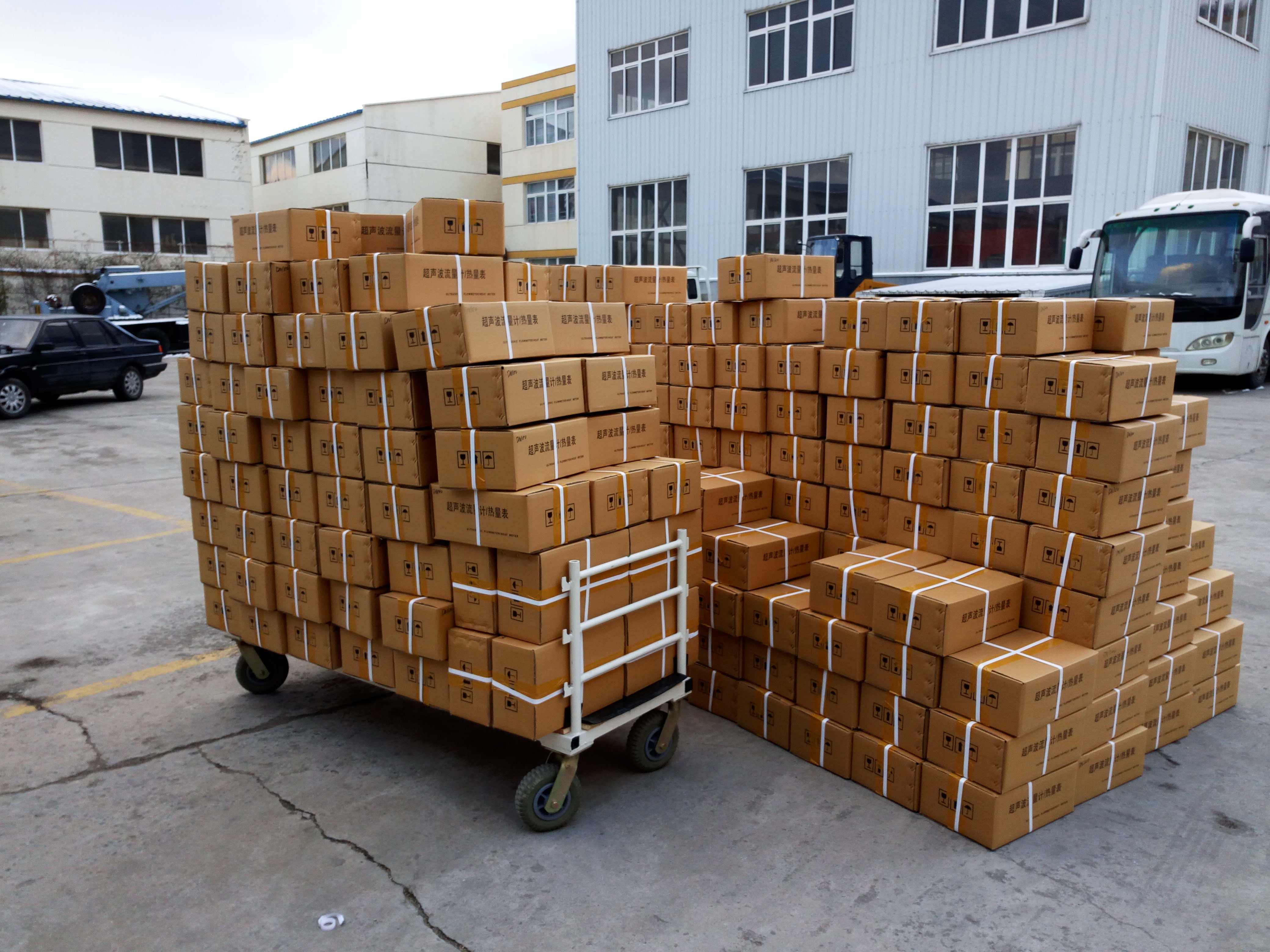
Factory shipment: sensor orders prepared for dispatch to EU and USA project sites.
Request a sample or quotation
Specify the project so the sensor platform can be matched to it: oil range required, turbidity band in NTU, solids band in mg/L, line pressure, process temperature, and fluid chemistry.
Contact: Michelle | Email: sales@kacise.com | Tel / WhatsApp: +86 180-6671-9659
WhatsApp: Start a conversation
XI'an Kacise Optronics Tech Co., Ltd. | 2nd Building, Tianyuan International Mansion, High-tech Zone, Xi'an City, Shaanxi Province, China | www.kcsensor.com
Have Questions or Need More Details?
Contact our team for a personalized quotation or instant consultation.
Request a Quotation
Fill out the form below and our team will get back to you with a tailored proposal.
WhatsApp Direct Chat
Prefer to chat in real-time? Message us on WhatsApp for instant assistance & quick answers.
- Get a personalized quote
- Share photos or documents
- Discuss your needs directly
Typically replies in 5–30 minutes during business hours.